Experimental Stress Analysis
The Essentials to a Successful Strain Gage Installation
The essential components of a successful strain gage installation can be outlined using the Pyramid Approach. We shall start at the bottom and build a solid foundation and work our way to the top of the pyramid.
Define the Test Program
We starting a strain gage project, it is critical to ask questions and find out as much information as practical so that you can have a successful result. The types of questions that need to be answered will generally fall into the following categories:
- Test Description- What is the purpose of this?
- Material to be Tested- The material properties will be needed in order to select the appropriate strain gage, adhesive and cleaning supplies.
- Gage Installation Environment- Is the project in a laboratory setting that is clean and dry or is the installation to take place outdoors in the winter?
- Instrumentation and Circuits- What is available for instrumentation and does it match the intentions of the testing?
- General Information- Document as much information as practical so that surprises are minimized later during the acquisition of the data.
Specimen (Key Areas of Concern)
- Coefficient of Thermal Expansion- Micro-Measurements can match the strain gage to many of the common materials used in construction in order to minimize the apparent strain due to a temperature change.
- Temperature Limits- Composites, plastics and some metals- Many of the adhesives require an elevated temperature cure so care must be taken not to exceed the limits of the material that is being tested.
- Solvent Sensitivity - plastics can be sensitive to the solvents that are found in the adhesive or used during the cleaning.
- Porosity - Concrete or rough castings; A rougher surface often requires a different type of handling to capture accurate measurements
Surface Preparation (Considerations)
- Surface Finish - In general, the surface should have some texture in order to promote adhesion. A rougher surface finish is recommended for high elongation measurements.
- pH value - Cyanoacrylates are sensitive to pH so the surface must be treated to ensure the appropriate level before bonding.
- Silicone contamination - This is very difficult to remove and often can be easily identified using a water break test. Machined parts, pumps, lotions, waxes are common sources of silicone and should be avoided.
- The proper surface preparation is very dependent on the material being tested. See Instructional Bulletin B-129 for more detailed information
Adhesive
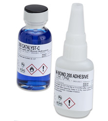
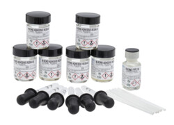
The adhesives used for bonding the strain gages are a critical component to the successful installation of a strain gage. The job of the adhesive system is to transfer the strain from the surface of the part being tested into the backing of the strain without the effects of creep. The adhesives that are selected for strain gage installation should be tested and qualified for strain gage use. The environmental conditions such as temperature and length of test should be considered when determining the right choice for your project. The most common types of strain gage adhesives are listed here below.
To review the full table of adhesives offered by Micro-Measurements visit our Adhesives page
Epoxies - A reactive epoxy resin plus hardener causes the liquid to polymerize into a thermoset solid. Room temperature stable for long periods. Room temperature or elevated temperature cure.
M-Bond AE-10 and M-Bond AE-15 are Micro-Measurements epoxy based adhesive systems.
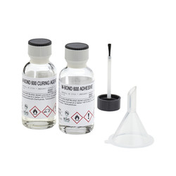
Solvent Thinned Epoxies - Mixture of reactive resins (usually epoxies). Heat cured to form solid, permanent bonds. Solvents allow for a thin uniform adhesive application, which greatly extends adhesive storage life. Phenolic resins are often combined with epoxy resins for formulation of high strength, high temperature adhesives.
M-Bond 600 and M-Bond 610 are Micro-Measurements solvent thinned epoxy adhesive systems.
Strain Gage (Selection Guide)
There are many different factors that go into the proper selection of the strain gage. Factors such as the operating temperature range, material being tested, required resistance; any many other aspects play an important role in determining the correct strain gage for your application. Consult our Technical Note TN-505 Strain Gage Selection: Criteria, Procedures, and Recommendations
Strain Gage Examples:

Foil types - Constantan and modified Karma are the most common alloys used for making strain gages. The Constantan is a nickel copper alloy wide used for general-purpose stress analysis and building transducers. The modified Karma is a nickel-chromium alloy has a wider temperature range and better fatigue endurance so it is often times selected for more hostile strain gage environments.
Choosing the Right Resistance:
Today we find that customers are selecting 350Ω strain gages and often times much higher. With the recent advancements made by with our Advanced Sensors Technology, we are able to produce strain gages in smaller sizes and much higher resistances than ever before, easily up to 5000Ω while maintaining tighter tolerances of ±0.2%. Advantages of higher resistance strain gages include longer battery life, much less leadwire desensitization and better signal to noise assuming the excitation is variable. Higher resistance values also allow using smaller grid dimensions while keep the excitation levels high with no risk of drifts.
Tests on plastic and other heat sensitive materials are becoming more stable and less susceptible to drift.
You can review our C5K gage series where we are constantly adding patterns and resistances to our product offerings. Matching 5000Ω Bridge completion Modules (BCM) allows to turn and Data Acquisition System compatible with high resistance strain measurement.
Gage-Leadwire Junction
Often times an afterthought, the gage-leadwire junction plays a very important role for a stable strain gage measurement. The most common practice is to create the junction using a soft, alloyed solder and a non-activated flux. With the right techniques, a stable junction can be created that will provide many years of service. In general, we recommend soldered connections as opposed to mechanical connections such as alligator clips or screw terminals as they are often times a source of instability.
Solder Types
|
Solder Type |
Solidus/Liquidus |
|
361A-20R 63% Tin 36.65% Lead 0.35% Antimony |
361°/361°F [183°/183°C] |
|
430-20S 3.7% Silver |
430°/430°F [221°/221°C] |
|
450-20R 5% Antimony |
450°/460°F [232°/238°C] |
|
570-28R 93.5% Lead 5% Tin 1.5% Silver |
565°/574°F [296°/301°C] |
|
Products shown in bold are RoHS compliant |
|
Leadwires (Selection)
There are several factors to consider when selecting the appropriate leadwire for a strain gage project. The factors include the following:
- Temperature capabilities
- Number of conductors
- Diameter of conductors
- Solid versus stranded
- Twisted and/or shielded
- Adhesion to environmental protection
The Micro-Measurements leadwire offerings can be found on the website under Accessories
Protective Coating
The strain gage performance is easily degraded by the effects of moisture, chemical attack, or mechanical damage. As a result, strain gages require varying degrees of protection according to the severity of the environment at the protective coating is the last line of defense between the environmental conditions of the test and the strain gage and adhesive system. Note the following:
- For long term tests or in particularly hostile environments, carefully clean the surface before applying the protective coating.
- Before applying any protective coating over an area that has been exposed to high humidity, dry the installation thoroughly.
- In general, a thicker coating offers a more resistant path to moisture absorption than a thin one.
A complete listing of Micro-Measurements protective coatings can be found at the following link on the website under Accessories, while help with selecting the appropriate coating can be found at Protective Coatings
Instrumentation
Micro-Measurements offers a comprehensive range of instrumentation from strain indicators to signal conditioning amplifiers to digital data acquisition systems. Our systems are designed to be turn-key so that the experimentalist can focus on the task of taking the experimental data. Some examples of the Micro-Measurements instrumentation is listed below:
The P3 Strain Indicator and Recorder along with the D4 Data Acquisition Conditioner and the MM01 Student DAQ are designed to be simple and user friendly. Simply un-package the instrumentation, install the software on the appropriate PC, and then the systems are ready for strain gage measurements within minutes of unpacking the units.

Digital Data Acquisition Systems
The newest data acquisition system to the Micro-Measurements product line is the 7100 System. We have taken our many years of experience in developing data acquisition systems and encorporated that into the 7100 System. A common list of features include the following:
- Stable, accurate, low-noise signal conditioning
- Individual input cards for strain gage and strain-gage based transducers, thermocouples, sensors with high level voltage outputs, and LVDTs
- Electronically selectable, built-in bridge completion for 120-, 350-, and 1000-ohm strain gages
- Scalable synchronized system (using multiple scanners)
- Maximum scan rate of 2000 samples per second (Radix-10). • Self-calibration traceable to NIST standard
- Simultaneous sampling with anti-aliasing ilter and analog-to-digital conversion for each channel
- Selectable digital iltering of measurement signals • High-speed Ethernet network interface with DHCP addressing

The System 9000 is intended for customers that require a higher rate of data acquisition. Features include the following:
• 12 Strain gage channels, supporting quarter, half, and full bridge strain gages and strain-gage-based transducers.
• 4 Plug-in card slots, available to support:
- High-level voltage signal
- Thermocouples
- Piezoelectric transducers (charge mode and voltage mode)
• Sampling rates: 50,000, 25,000, 10,000 and 5,000 samples/second.
• Synchronized sampling of all channels.
• Expansion to a 48-channel system: Up to three scanners can be combined to provide 48 fully synchronized channels (36 strain gage plus 12 configurable).
• On-board Data Recording: Supports manual, time, and limits-based recording. Pre- and post-trigger data are available for limits-based recording and manually-triggered recording.
• Self-Calibrating (Optional) using NIST-traceable voltage calibration card (Model A123). Provides a high-accuracy voltage source used to calibrate the gain and offset of each channel. A123 is removable and interchangeable and it only needs to be present in the Model 9000 during the self-calibration process.
- Optional analog outputs (Model 9000-16-SM-AO): Provide an analog output for each of the twelve strain gage channels. Bandwidth DC to 19.8 kHz.

Specialty Purpose Instrumentation
Micro-Measurements also offers a line of specialty instrumentation that is designed for purposes such as checking the electrical properties of the strain gage, calibrating the strain gage instrumentation, or welding strain gages onto steel structures. Some examples are following:
GIT-1300 Gage Installation Tester
The 1300 Gage Installation Tester is used to verify the quality of an installed strain gage (strain gauge), as well as the complete gage installation, including leadwires. A carefully selected individualized test voltage is used for each measurement mode. Operation is by push buttons.
• Compact size
• Battery operated convenience
• Reads insulation resistance to 20 000 megohms
• Measures deviation of installed gage resistance to 0.02%
• Ohmmeter scale available for troubleshooting• Verifies the complete installation, including leadwires

Model 1550B Strain Indicator Calibrator
A true Wheatstone-bridge simulator, the 1550B Strain Indicator Calibrator presents known and repeatable resistance changes to the input of the indicator. Three decades of push buttons are used to produce incremental resistance changes. The 1550B is NIST-traceable.
• Simulates 120- and 350-ohm quarter, half and full bridges
• Strain range of ±99 000 microstrain in 100 microstrain increments
• Transducer range of ±49.95 mV/V in 0.05 mV/V increments
• Reverse switching for plus and minus calibration
• High precision Bulk Metal(R) foil technology resistors used throughout
• Accuracy of 0.025%, NIST traceable

Model 700B Welder
Model 700B is the next-generation of Micro-Measurements Model 700 Welder that has been used for decades for installing tens of thousands of strain gages world wide. It was developed based on this experience along with customers input and support, to provide more capability and flexibility, all the while being offered in a smaller, more portable package. Features include the following:
- Light weight and compact size.
- Weld energy is continuously adjustable from 10 to 60 joules, making the Model 700B an excellent choice for installing weldable strain gages and temperature sensors, as well as small thermocouples and light-gage metal.
- Fast welding rate – up to 60 welds per minute
- Replaceable rechargeable battery allows smooth continuous operation.
- “Low-battery” indication to warn the user when the Li-ION battery requires charging.
- Optional carrying bag with shoulder strap and belt loops providing convenient storage space for cables, batteries, battery charger welding tips and instruction manual

We have now completed the Pyramid! I hope that you have enjoyed the journey and found this information useful.


